Case conversion: IBM PS/2 Model 95
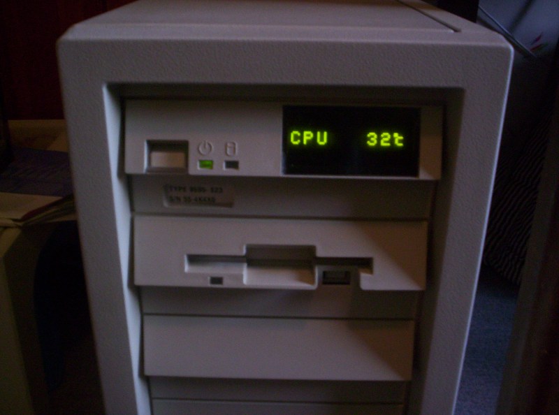
The operator panel in action.
To preserve the look of the case I wanted to use the original operator panel. To convert it to ATX I had to:
- Make the power swich spring back when pressed
- Find the pins for the speaker, HDD LED and power switch
- Find the pins that power the panel
- Find a way to communicate with the LED displays via the PC's parallel port

IBM PS/2 server operator panel.
The first point was taken care of by removing a piece of metal from the power switch. Finding the pins for all the other stuff just took some probing around with a multimeter. The power LED doesn't need to be connected to the PC motherboard as it automatically lights up when the operator panel is powered.

Converting the power switch to a pushbutton.
The LED displays (HDLG 2416) were much more challenging (and interesting). I really wanted to be able to use them for that authentic touch. First I planned on finding what pins on the op panel connector they used and driving them directly, but that proved difficult. I couldn't find all pins on the connector because some were connected via logic chips, which probably tie into the serial link I eventually chose to use. Thankfully, I managed to find a snippet of an IBM patent on Louis Ohland's site. The snippet talks about the serial connector, but doesn't include any pictures, pinouts or a description of how the characters are actually sent to the displays. The complete patent document is long gone from IBM's site and can only be downloaded for money from others. It was reverse engineering time.

Experimenting with the displays.
After some more multimetering and looking at data sheets I found the two correct pins on the six pin serial connector. To experiment with the protocol, I made a simple C program to talk to the panel over the parallel port. Sending characters to the display wasn't that difficult; sending characters that actually made any sense was. At first I assumed all characters would be sent sequentially and that the panel's logic would put them on the correct LED digit, but after looking at the screwy characters that appeared I discovered that the character codes that are actually sent are 8*[ascii code]+[no. of digit]. So the panel's logic basically does a Mod 8 on the incoming value, uses that to determine what digit to use and then puts the rest of the value divided by eight on that digit.
This means that individual characters can be changed, but in my software I chose to just always overwrite all characters with an 8-character string. The protocol is surprisingly robust. The displays work perfectly with both my 150MHz and 3.2GHz computers, and I even ended up controlling the output pins simultaneously instead of sequentially when changing states. The software to send a string to the displays can be downloaded here (also includes source code and schematic). Update: to function on Vista/Win7 inpout32.dll from here is needed and the driver must be installed using the 'installdriver.exe' file.
When the communication with the displays worked, I wrote a Windows service that starts Speedfan to get the system temperatures and displays those along with some other info such as the amount of free memory. Click here for a little movie showing the panel software in action.

The operator panel control service.

The final schematic. This is incorrect, the HDD LED requires an inverter; the motherboard pulls it to ground but the Operator Panel expects 5v to be switched.
As can be seen the schematic includes a diode. Due to how the panel works the orientation of the power switch connector actually matters. Without the diode, if the orientation is wrong the PC starts up as soon as it gets mains power; with the diode, the power switch does nothing.

The adapter I made to connect the operator panel to a standard PC. Like the motherboard tray, the motherboard pin cables were taken from a donor case. The flatcable is a floppy cable.

The very simple cable to connect the serial display control port to the pc's parallel port.

IBM thoughtfully provided mounts for a second print under the operator panel.

Mounted and connected. The adapter print is mounted upside down so there's room for the cables and it's wrapped in paper and electrical tape to prevent it from making contact with the operator panel.